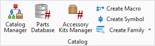
Create Symbol
The Symbol Creation Wizard lets the user define a new symbol.
Accessed from:
The dialog consists of step buttons on the left and a settings area on the right. There is an Auto Hide button in the lower left corner of the dialog that sets whether or not the settings area will be hidden if you move the cursor back to the drawing area (so it is not in the way). If Auto Hide is turned on, you can click on the desired step button to display the setting area again. The Symbol Creation Wizard can also be used to modify an existing symbol.
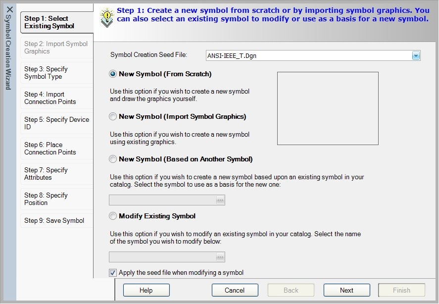
Step 1: Select Existing Symbol
| Setting | Description |
|---|---|
| New Symbol (From Scratch) | Select this option if you are creating a new symbol that will be added to the catalog and you will be drawing the graphics as you create the symbol. |
| New Symbol (Import Symbol Graphics) | Select this option if you are creating a new symbol that will be added to the catalog and you will be using existing graphics (blocks or cells or elements on a drawing) while creating the symbol. |
| New Symbol (Based on Another Symbol) | If you wish to select an existing symbol on which to base the new symbol, select this option. A field is provided where you can enter the existing symbol's name or select the browse button to display the Select Symbol dialog from which you can preview and select a symbol. |
| Modify Existing Symbol | If you merely wish to edit some aspect of an existing symbol (without creating a new symbol), select this option and use the Browse button to select it. |
| Apply the seed file when modifying a symbol | When you select this check box, the software will use the seed file defined for symbol creation when modifying a symbol. This seed file is selected in the Systems Paths tab of the Setup dialog. |
Step 2: Import Symbol Graphics
The following dialog will appear if you selected the New Symbol (Import Symbol Graphics) option in step 1 (if you did not, continue to the next step). This step enables you to define the graphic elements of the symbol.

| Setting | Description |
|---|---|
| Select Objects | To select elements in the current page, select the Select Objects button. In the drawing screen, you will be prompted to select objects. Click on or window around the objects that will make up the symbol. Press <Enter> when all items have been selected. Select the Next button to continue to the next step. |
| Clear Selection | If you wish to de-select the objects you have selected, click on the Clear Selection button. |
| Block/Cell | To use an existing block, select the Browse button next to the Block/Cell field. Browse to the desired block file and select the Open button. The path and filename for the block or cell will appear in the Block/Cell field. If the block contains attribute text, select the Extract Block Attributes button to list these in the Mapping Attributes area of the dialog. You can then use the right-hand column to assign these to a corresponding OpenUtilities Substation attribute. |
| Attribute | When you click in the Attribute column, a list of available attributes will appear from which you can make a selection. |
Step 2 (From Scratch): Specify Symbol Type
If you are creating a symbol from scratch, a blank drawing screen will appear. Draw the symbol graphics using the line, circle, rectangle and other drawing tools as needed. Use lines, not wires to draw symbol graphics. Be aware of the grid spacing that will be used in your drawings so that connection points are properly spaced; connection points must always be on this grid. When the desired graphics are drawn, return to the Symbol Creation Wizard and continue. This step enables you to define the characteristics of the symbol that determine how the symbol behaves in drawings.

| Setting | Description |
|---|---|
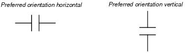
| Preferred Orientation | Determine how the software will look at the symbol when generating a connection list. It also determines how wires will be broken or closed when the symbol is placed or moved. Select Horizontal if the symbol is to be scanned from left to right (in other words, if the wire will be horizontal in relation to the symbol). Select Vertical if the symbol is to be scanned from top to bottom (i.e., if the wire will be vertical in relation to the symbol, as in IEC format drawings). |
| Cross Reference Prefix | As an option, you can specify a prefix for the cross reference for this symbol. In the Cross Reference Prefix field, select a prefix from the drop-down list (NO, NC, INPUT, OUTPUT). If you wish to accentuate this cross reference text, there is an underscore setting in the Device Cross Referencing dialog. |
| Symbol Type | Select the symbol type that best matches the symbol you are creating. |
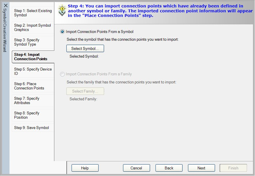
Step 3: Import Connection Points
This step allows you to import connection point designations from an existing symbol or family. These can then be used in the Place Connection Points step, saving you from having to remember and re-enter this information. If you don't wish to import connection points, select Next to go to the next step. If you are basing the new symbol on an existing symbol (selected in step 1), the connection points of that symbol will appear in the drawing area when you define the device ID in a later step, so you can skip this step.
| Setting | Description |
|---|---|
| Select Symbol | Displays the Select Symbol dialog from which you can preview and select a symbol. |
| Import Connection Points From a Family | If you are creating a panel layout or wiring diagram symbol, this option will be available allowing you to import connection designations from parent and child symbols at the same time. Use the Select Family button to select the desired family. |
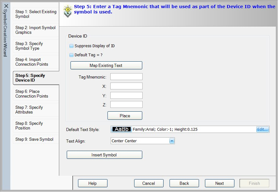
Step 4: Specify Device ID
In this step, you enter a tag mnemonic. This is the portion of the device tag that will be given to every instance of this symbol, such as "K" or "CR" for a relay.
| Setting | Description |
|---|---|
| Suppress Display of ID | Select this option if you wish the device ID to be suppressed by default. When the symbol is placed, the Suppress Device ID option in the Device Properties dialog will be selected by default. |
| Default Tag = ? | Select this option if you wish the user to be prompted to enter the device tag when the symbol is placed instead of having the software automatically assign the device tag. Typically this is done for child symbols so that you can associate the child symbol with the device tag of a selected parent symbol. When the symbol is placed, the Device Tag field in the Device Properties dialog will show the tag mnemonic followed by a "?". |
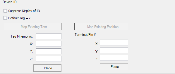
| Tag Mnemonic | Enter the desired character(s) for the tag. Then select the Place button to select a position for the device tag by clicking in the drawing. After you select a position, the dialog will reappear with the coordinates of the selected point in the X and Y fields. Coordinates are from the drawing origin. You can adjust the values, if desired. |
| Terminal/Pin # | If the symbol type you selected in step 2 was Terminal or Plug, there will also be Terminal/Pin # fields in the dialog. The Place button for these fields allows you to select a position for the terminal block number on a terminal symbol. In other words, the device tag will identify the terminal strip and then you will have this second value to identify the block within the terminal strip. Similarly, for plug symbols you can pick a position for the pin number. After you pick a position, the coordinates will appear in the X and Y fields. |
| Default Text Style | Sets the appearance of the device tag. Select the Edit button to display a dialog where you can make various text settings. |
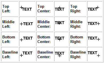
| Text Align | Sets the orientation of the text to the point that is selected. Text will be placed in relation to the selected point as shown: |
| Insert Symbol | Use this option to place an existing symbol in the symbol you are creating. This is useful, for example, if you wish to put contact symbols in a cross reference symbol for a relay or add fuse symbols to a disconnect switch. When you select the button, the Insert Symbols dialog appears, allowing you to select a symbol. If you only want the graphic portion of the symbol you are inserting, you will have to delete the unwanted connection points, etc. |
Step 5: Place Connection Points

| Setting | Description |
|---|---|
| Number of Connection Points | If you have imported connection points in an earlier
step or are basing the new symbol on an existing symbol, the connection points
will be listed. If not, enter the number of connection points that the symbol
will have in the
Number of Connection Points field. Press
the
<Enter> key. Fields will appear for
the number of connection points that you entered.
For each connection point, enter in the
Visible Text field any connection point
designations that you wish to appear beside the connection point. If you want
hidden text to be associated with the connection point, enter it in the
Hidden Text field.
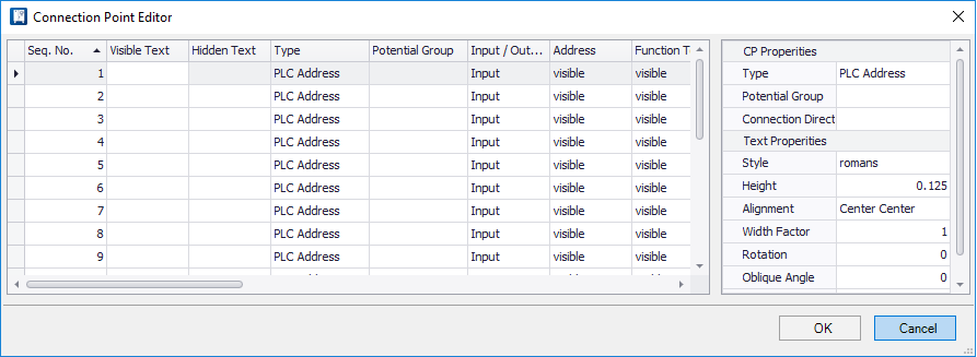
In the Type column, select the type of connection point being defined. The choices in the drop-down list will vary depending on the kind of symbol being created. Choices include Schematic, Hydraulic, Pneumatic and PLC. Note: When creating
a PLC symbol, the connection points order needs to include all of the addressed
connections in order. Non-addressed connections need to appear after the
addressed points. This also applies to PLC families (children with addresses
should appear before children without addresses).
In the Potential Group field, you can assign a potential group name. Usually each connection point has a different potential group name. If you make no entry in this field, the software will assume the connection points have different potential groups. However, if two or more connection points on the symbol are given the same potential group name and are connected to wires, the same potential (wire number) will be assigned to these wires. In other words, the potential will carry through the symbol. This is useful when working with flex I/Os. Note: When creating
terminal symbols, the same potential group name is assigned to all connection
points by default.
If you are creating a terminal or plug symbol, there will be a Configuration field for each connection point where you can designate which side of the terminal or plug the connection point is to represent, or if it is to be a jumper. |
| Array | If you check the Array option you will be able to place a group of connection points in one step (use the Select All button and when you place the connection points). The Array dialog displays letting you define the number of rows and columns, enter spacing (offset) values for the connection points and set the placement priority for rows and columns. |
| Select All | Use the Select All button if you wish to select all the connection points and place them one after another. |
| Place | When you are ready to position the connection points, select one from the list and select the Place button. Following the prompts on the command line, select the position for the connection point and then the position for the connection point text. Repeat this step for each additional connection point. |
| Text Align | Set the orientation of the text to the point that is selected. |
| Connection Point Editor | If you select the Connection Point Editor button, all the connection points will be listed together in a table-format editor allowing you to easily edit various parameters. It is possible to select multiple connection points in this editor and assign the same value to all of them. |
| Map Connection Point Text | If you imported an existing block with attributes in an earlier step, you can use the Map Connection Point Text button to select the existing text and then choose a connection point position. Follow the prompts. |
| Default Text Style | Sets text parameters for the connection point text (before they are placed). There are separate fields for Connection Point, PLC Address and PLC Function Text. These settings can be overridden by the Use Text Style check box under Symbol Text in the project options Text Settings dialog. |

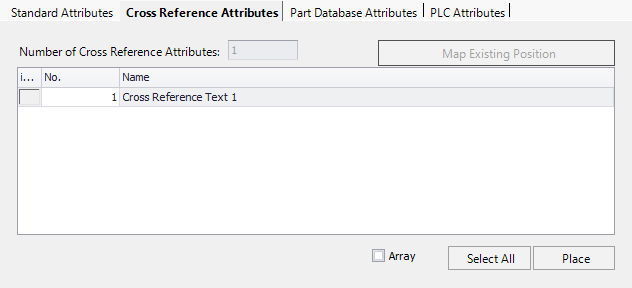
Step 6: Specify Attributes
There are tabs that group the available attributes into Standard Attributes, Cross Reference Attributes and Part Database Attributes. Cross reference attributes for each defined drawing mode are available (i.e., Panel_Layout_XRef, Single_Line_XRef, etc.). Including this attribute on the symbol causes the page and line number of the symbol in that mode to be displayed.
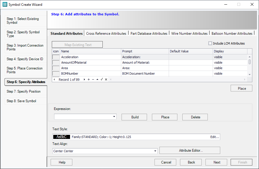
Symbol attributes can be set up to prompt for text that is entered by the user at the time the symbol is placed.
| Setting | Description |
|---|---|
| Map Existing Text | If you are basing the symbol on imported symbol graphics with attributes, the Map Existing Text button will be active. This allows you to map an attribute from the list to one that exists in the drawing. Select the desired attribute from the list, select the Map Existing Text button, and then click on the desired attribute in the drawing. |
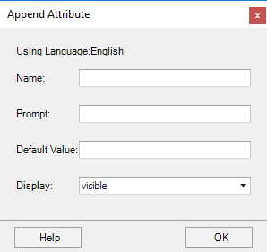
| + Button | If you wish to add an attribute to the list of attributes, select the + button at the bottom of the list. The Append Attribute dialog will appear. Enter values for the name of the attribute, a prompt that will appear when the symbol is placed, a default value, and whether the attribute will be visible or invisible in the drawing. Select the Use same text check boxes to use the same values in all languages. Select OK to enter the new attribute. It will now be available when creating new symbols. |
| Place | Select the desired attribute from the list and then select the Place button (the one immediately below the attribute list) to place in on the symbol. After you place an attribute in the drawing, it will be marked in the list with an "X" in the left-most column. |
| Default Value | If you wish a particular value to be assigned automatically to this symbol whenever it is placed, scroll down to the relevant attribute and enter the desired value in the Default Value column. For example, you can enter a part number for the PartNumber attribute that you always want to assign to this symbol. |
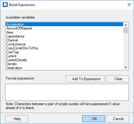
| Build | If you wish to combine attributes, select the Build button to display the Build Expression dialog. Here you can select and combine attributes into an expression. Select an attribute and use the Add to Expression button to add it to the expression displayed at the bottom of the dialog. Select OK to return to the Symbol Creation Wizard and then use the Place button to place the expression. |
| Text Style | Sets text parameters for the attribute texts (before they are placed). |
| Text Align | Sets the orientation of the text to the point that is selected. |
In the Cross Reference Attribute tab you can set the position of cross references that appear at the symbol. This positioning has priority over the positioning that can be set in the project options, Device Cross Referencing dialog. The cross reference attribute can be placed on a standard symbol to control the position of cross reference text if it is a child symbol or duplicate ID.
This lets you add a wire number attribute for each terminal in your wiring diagram terminal strip symbol to control where the wire number for that terminal is displayed. It's useful if you wish to display the wire number in the center of the terminal and then print the from-to connections on either side of it.

The value of the Wire Number Attributes should match the number of terminal numbers defined for the symbol.

You can define the number of balloons to be placed (if multiple part numbers are associated with the symbol).
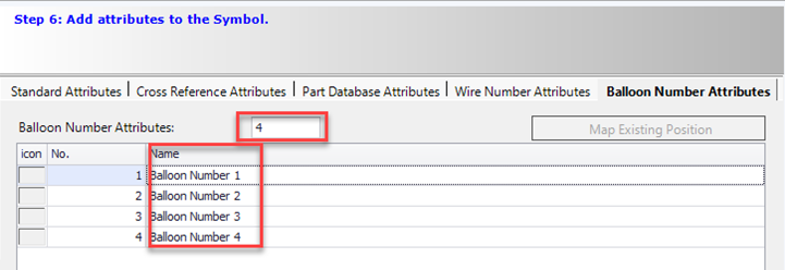
Use the Place option to position all of the balloons. The (X) in the icon field indicates the balloon has been placed.

Once the part numbers are defined for the symbol the balloons will be automatically placed at the locations defined.

Step 8: Specify Position
In this step, you select the insertion point for the symbol and for the cross reference text (if any).

| Setting | Description |
|---|---|
| Insertion Point | The insertion point represents the cursor position when the symbol is placed in the drawing. It determines how the symbol is placed in relation to the selected point. Use the Pick Point button and click on the desired point in the drawing screen. The coordinates of the selected point will appear in the X and Y fields. These values can be adjusted if desired. |
| Snap to End Point | Select the Snap to Endpoint check box if you wish the symbol to automatically snap to the nearest endpoint of the wire upon which it is placed. This feature is often used for wire link symbols and PLC child symbols. |
| Cross Reference Symbol Position | The cross reference symbol position will determine
where the cross reference symbol for a parent symbol will appear in relation to
the symbol (if there is a cross reference symbol). Use the
Pick Point button and click on the desired
point in the drawing screen. The coordinates of the selected point will appear
in the X and Y fields. These values can be adjusted if desired. Use the
Delete button to remove a selected point.
The cross reference symbol on a parent is controlled by the following settings in order of priority:
|
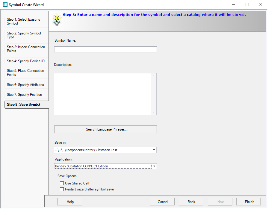
Step 9: Save Symbol
In this step, you enter the symbol's name and description and select a catalog in which it will be saved.
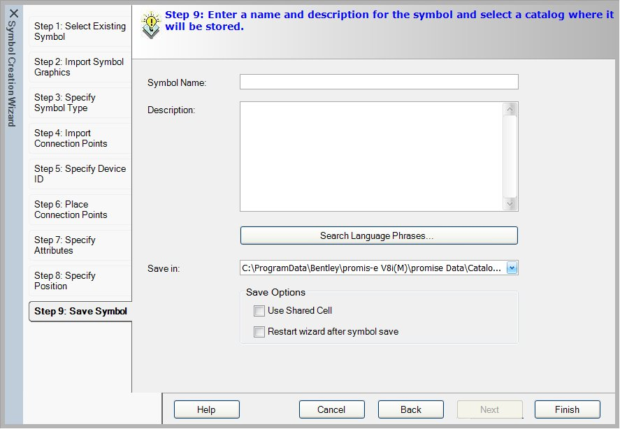
| Setting | Description |
|---|---|
| Symbol Name | Enter a name for the symbol. |
| Description | Enter a description for the symbol. |
| Search Language Phrases | Use the Search Language Phrases button to select and place phrases from the language database into the Description field. These phrases are displayed in the language that is currently selected (Project Options, Region Settings). |
Save Symbol to Components Center
If you have the Components Center option enabled then when you create a new symbol you are prompted to save the symbol to a catalog in the Components Center.